Jeroen's Project Journals
Audio amplifier

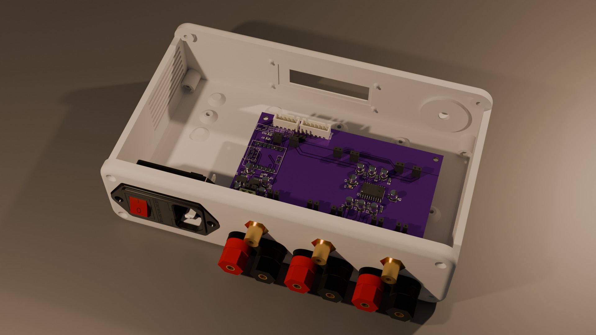
3-channel audio amplifier. Mains-powered and with digital volume control. Includes a 3D printed enclosure matching the Teensy DSP/DAC, OLED display and rotary click-encoder control
- Gallery
PT2258 Volume Control
2024-01-09
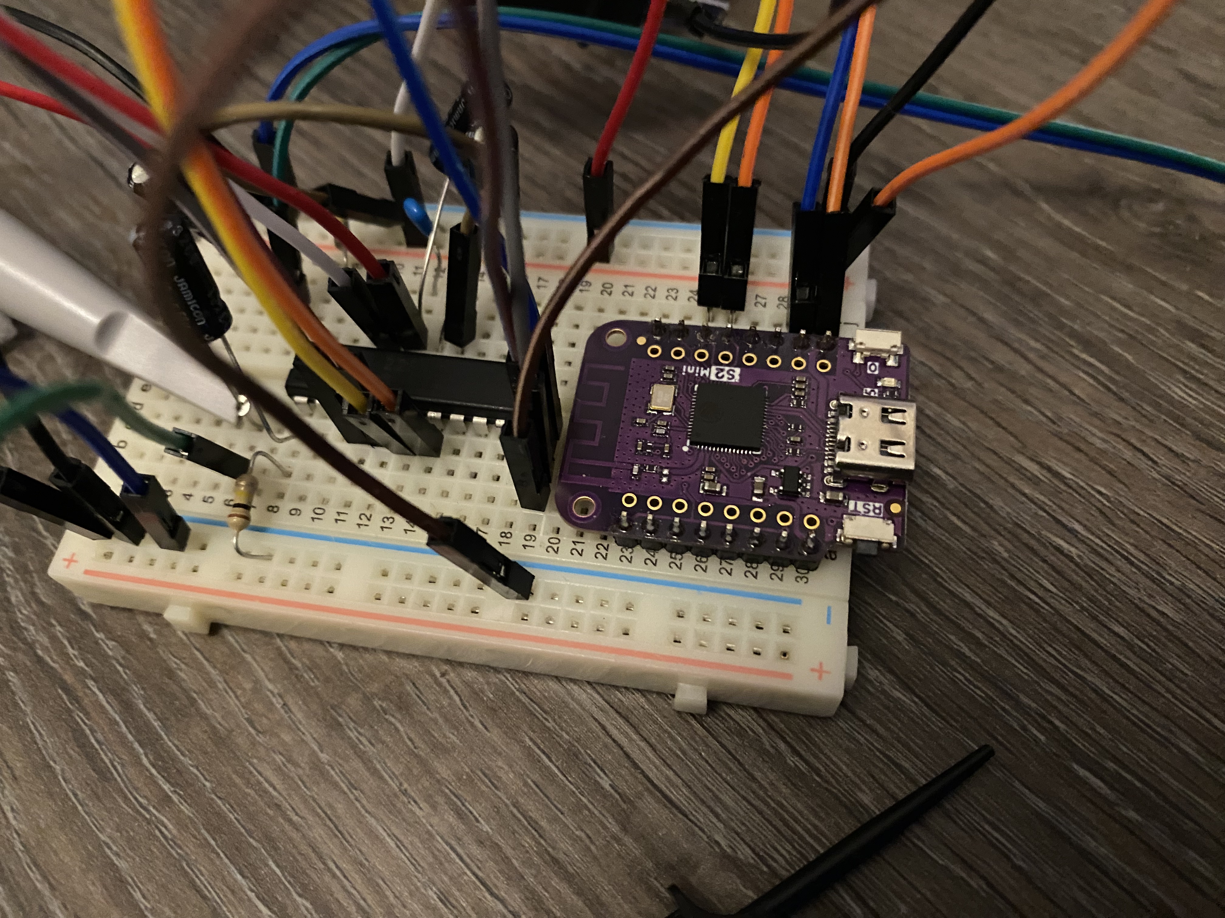
The PT2258’s arrived, and I built a breadboard version of the reference schematic found in the datasheet:

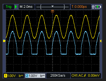
I had to use a Wemos S2 mini microcontroller board I had lying around, since apparently the Seeed Studio XIAO SAMD21 I was going to use for this had its I2C peripheral destroyed. At first I got some horrible distortions of the signal. This is what the chip did to a pure sinewave input:

After asking around on the diyaudio forum someone suggested the amplitude of the input signal may be too high. This wasn’t the case, but it did make me realize the supply voltage may be the culprit. I was supplying the PT2258 with 5V, since that made sense and it should work according to the datasheet. But the nominal Vdd is specced at 9V. With some trickery starting with 5V, getting the chip up and running, then disconnecting the S2-mini and THEN increasing Vdd to 9V (which would blow up the S2-mini) I found out this does indeed solve the problem. No more clipping to be seen, even at the maximum amplitude achievable by the PCM5102A (2.1 Vrms).
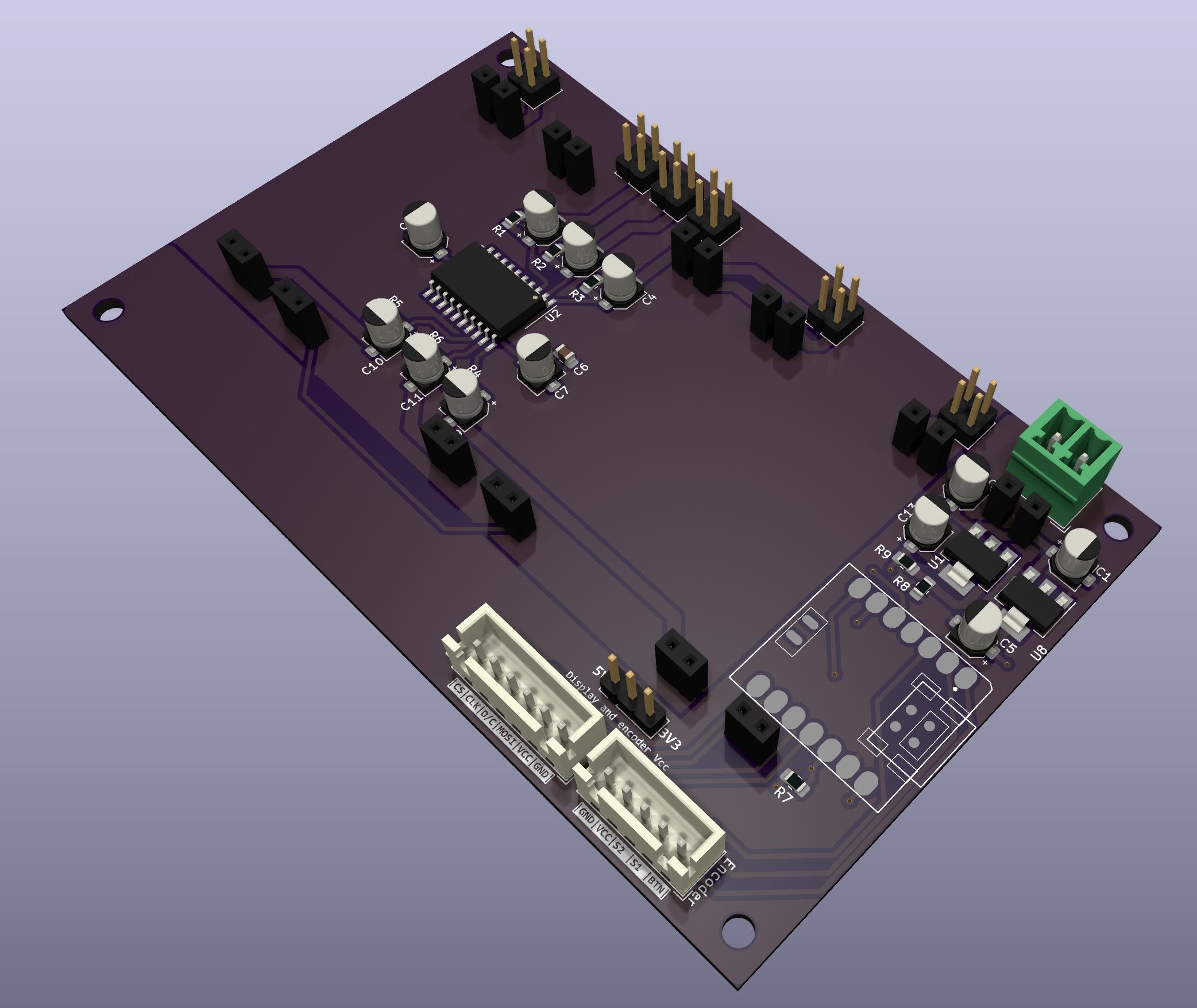
So that meant I had to update the design of the carrier-board to include a 9V supply. Here’s a pretty picture of the current iteration:
