Jeroen's Project Journals
Audio amplifier
3-channel audio amplifier. Mains-powered and with digital volume control. Includes a 3D printed enclosure matching the Teensy DSP/DAC, OLED display and rotary click-encoder control
- Gallery
Introduction
2023-12-26
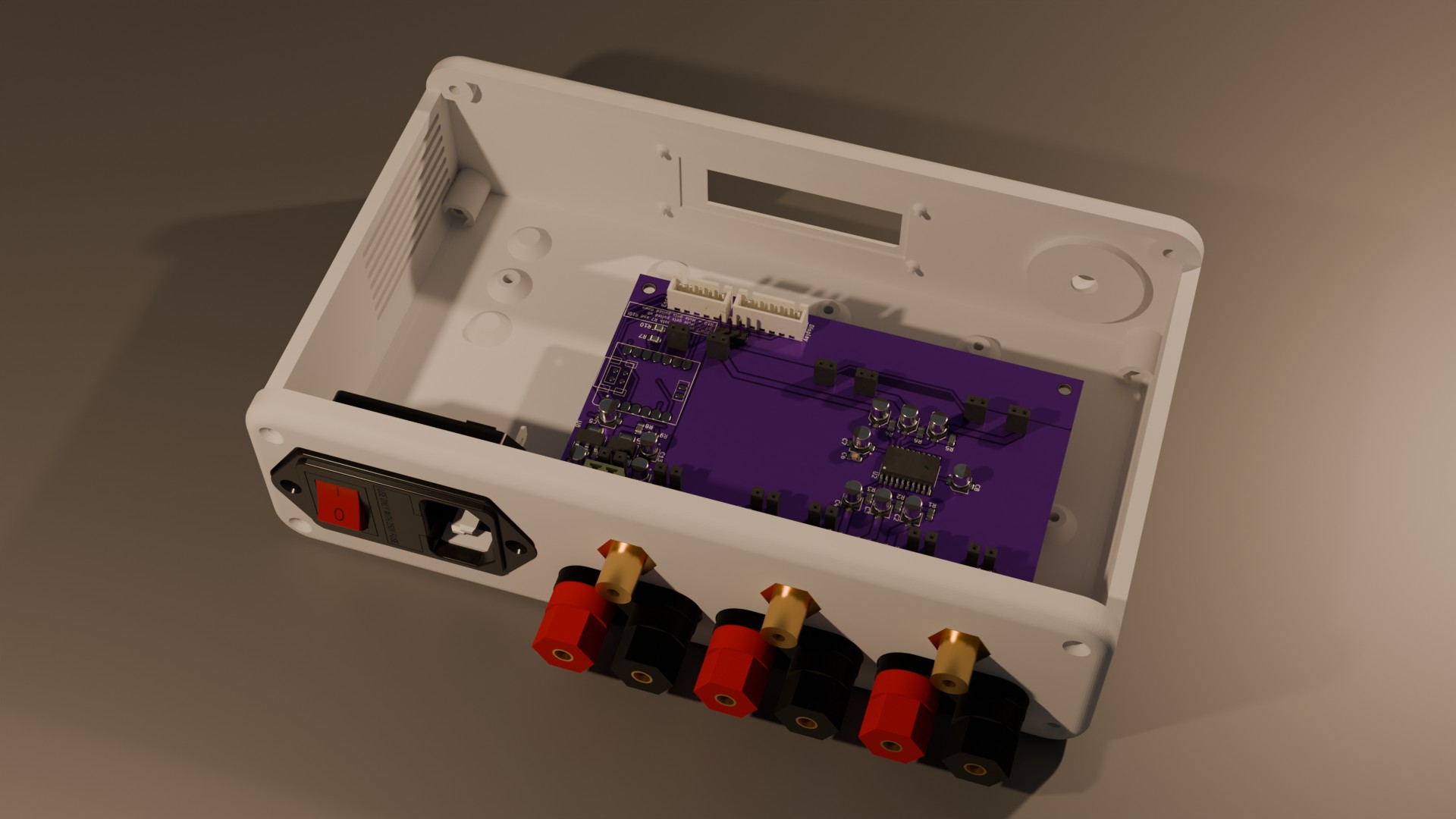
For my Concrete Subwoofer, along with a DSP/DAC, I needed an amplifier. I decided to create a 3-channel amp using cheap mono amplifier modules based on the TI TPA3118 class-D amplifier chip. These modules are cheap and I already had one lying around from another project. So I ordered 2 more and designed an enclosure with room for the 3 modules and a small MeanWell power supply, a front-panel fitting a rotary encoder and display and a rear-panel with the mains inlet, line-inputs and speaker-level outputs:

A preliminary wire-up of these modules using my bench power-supply and soldered-on wires actually sounded surprisingly well. Unfortunately, it turned out these are hardwired with a 36 dB gain. Combined with the 2.1 Vrms of the DAC IC’s I used this made for a monstrous speaker-level signal. The only way to use this setup was with drastic digital attenuation, which audibly reduced the sound-quality, given the DSP/DAC can only do 16-bit audio using the Teensy Audio Library. For this reason I decided to reduce the gain. The gain of the TPA3118 can be set to 20, 26, 32 or 36 dB using a voltage divider on one of the pins:
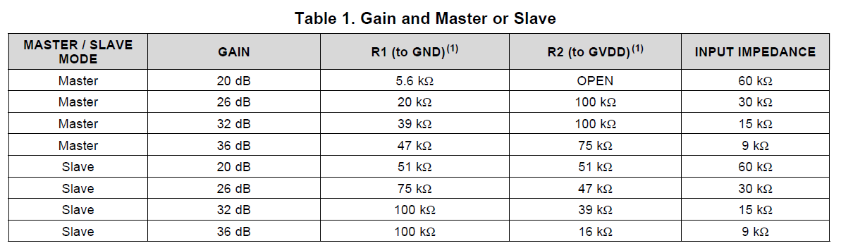
So from this table I had to replace R1 with a 5.6k resistor and remove R2 entirely. I didn’t take any before-pictures, but this is what that looks like after the mod was done, and after I added some connectors:

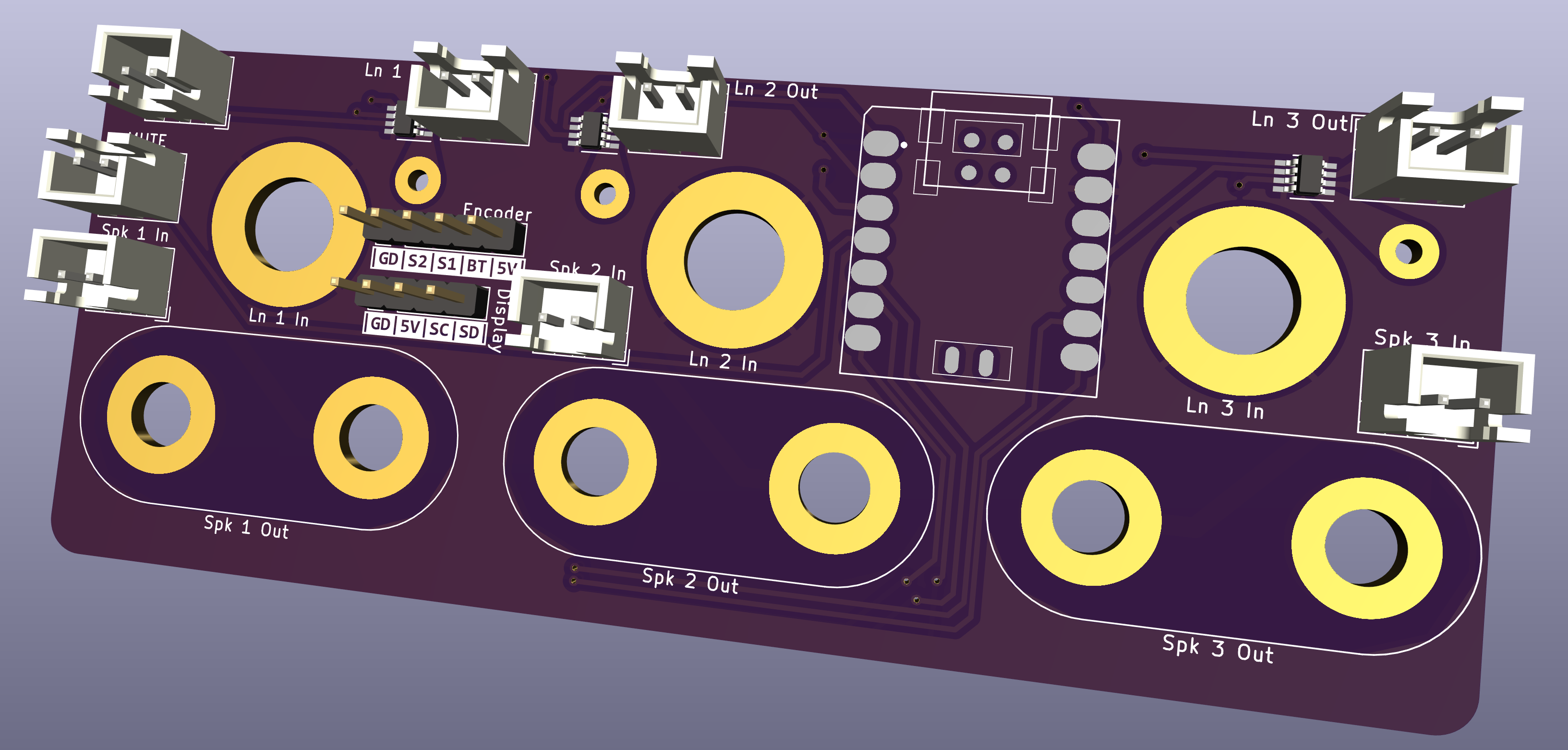
This helped, but the volume was still pretty deafening, so I decided to add analog volume control to the line-level inputs using a simple voltage-divider circuit, digital potentiometers and a microcontroller. I designed this PCB, and had it fabricated (bare PCB only) by JLCPCB:
The idea of this design is to have it held in place by the nuts of the RCA connectors and binding-posts. This part worked very well, and you can see what that looks like here:

Unfortunately the sound-quality with this circuit in the loop became abysmall. I also may have blown up the amplifier modules becuase I had a solder-bridge in one of the digital potmeters. At this point, no matter what I do, if I have speakers connected to the output-side they start making a terrible noise as soon as I connect anything at all to the input.
So that’s the current status of the project. I have to investigate why the amplifiers have become so noisy. It might be because of the power supply. For my early tests I used 12V, but I changed this to 5V so I could power the volume controller directly. As it turns out these modules require at least 8, 10 or 12 Volt (depending on where you look), so that might have something to do with it. If this is it then I’ll have to revert to using the 12V supply I used earlier.
Next step is to redesign the volume controller. I think it was a mistake to connect all grounds together, so I’ll have to change that at least. I also want to look at making a carrier-board for the amplifier modules, and that could have the volume controller on-board. If I could then find a good way to connect that carrier-board to the back-panel connectors I could eliminate most wiring inside the enclosure.