Jeroen's Project Journals
Audio amplifier

3-channel audio amplifier. Mains-powered and with digital volume control. Includes a 3D printed enclosure matching the Teensy DSP/DAC, OLED display and rotary click-encoder control
- Gallery
PCB doesn't work
2024-08-18
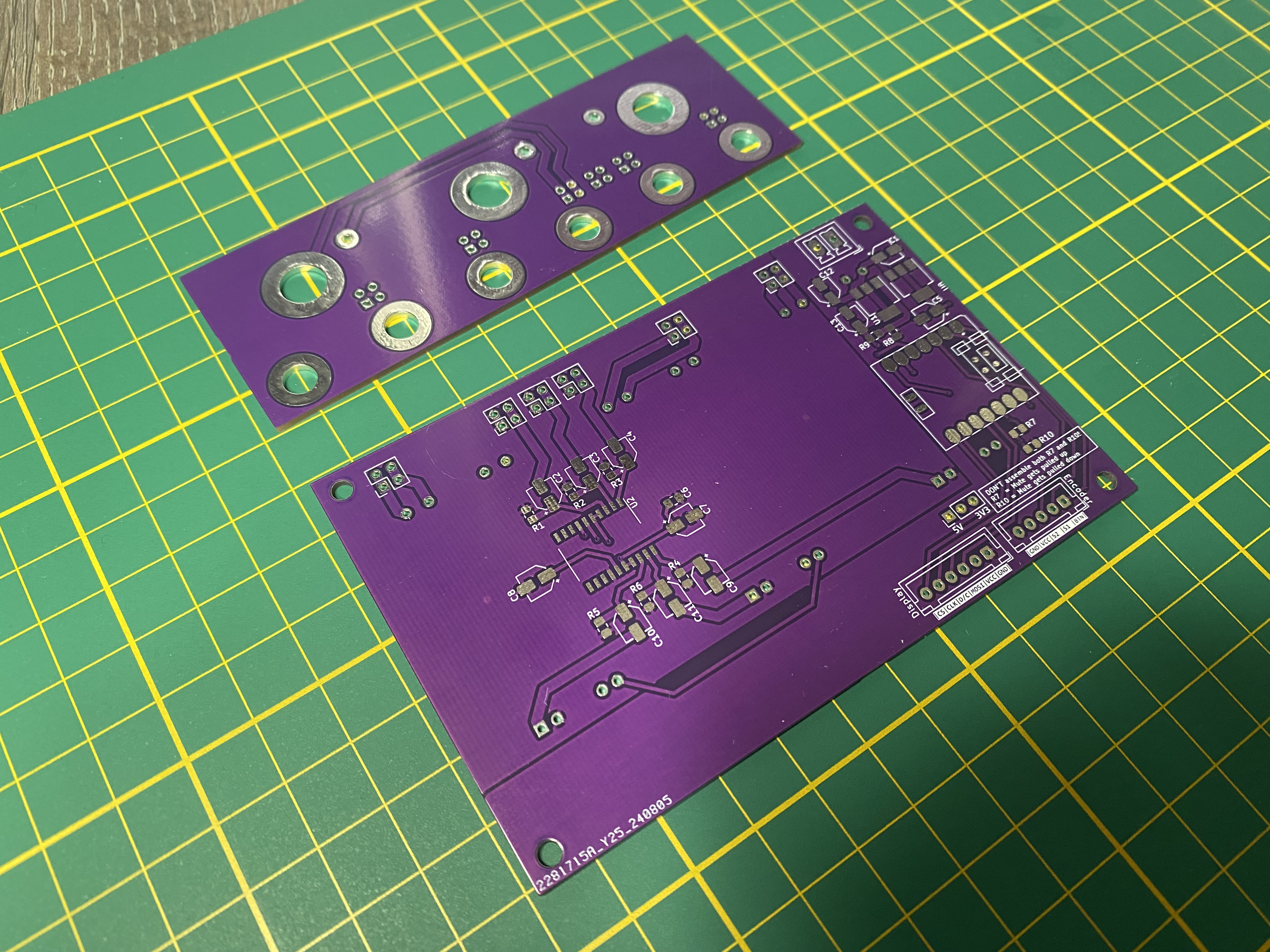
This project was on the backburner for quite a while, but a few weeks ago I finally ordered the PCB’s, and they arrived last week:

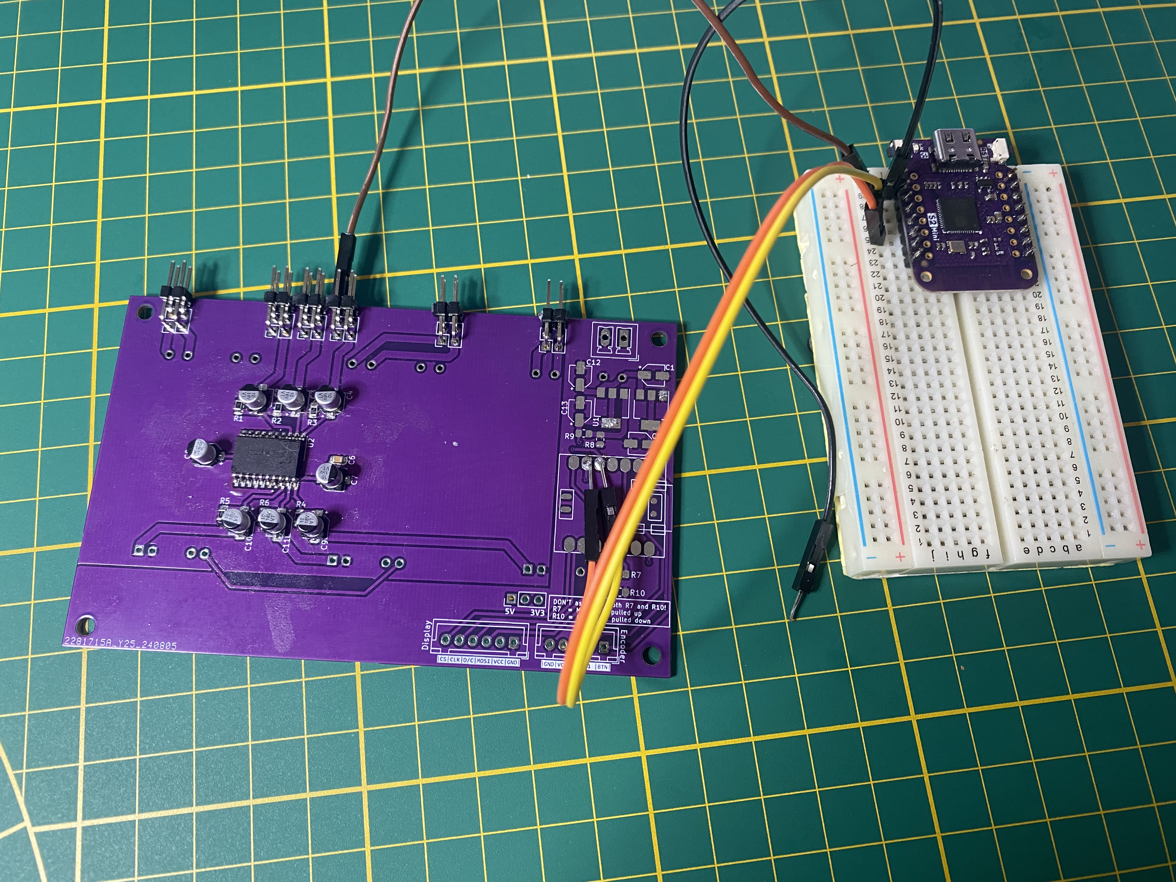
After assembling the PT2258 and the surrounding capacitors I didn’t stop to think but simply hooked up the I2C lines to the S2 mini, connected the 9V rail to my bench power supply, connected all GND’s together and plugged a USB cable into the S2 mini:

Unfortunately, the S2 couldn’t initialize the volume controller chip, and after some poking around I realized the I2C lines were pulled up to almost 9V! So I may have fried the I2C bus on the S2 mini.
After some tinkering and head-scratching I did what I should have done before all of this and went back through my earlier notes. This particular bit caught my attention:
D’oh! So I overlooked a crucial thing in my design: I should have added a level-shifter between the microcontroller and the PT2258. I2C does not specify a voltage level, and with a 9V supply the PT2258 uses 9V as the signal level for the I2C bus. The S2 mini and the XIAO ESP32C3 (which the PCB is really designed for) both use a 3V3 signal level.
So at the very least this requires a pretty significant patch of the PCB: cutting the SCA and SDA lines and somehow mcgyvering a level-shifter in between. I’ll definitely give it a try first, and then decide whether to use the PCB as-is with the patch in place, revise the PCB and re-order, or give up altogether and simply buy an off-the-shelf amplifier (but where’s the fun in that!).