Jeroen's Project Journals
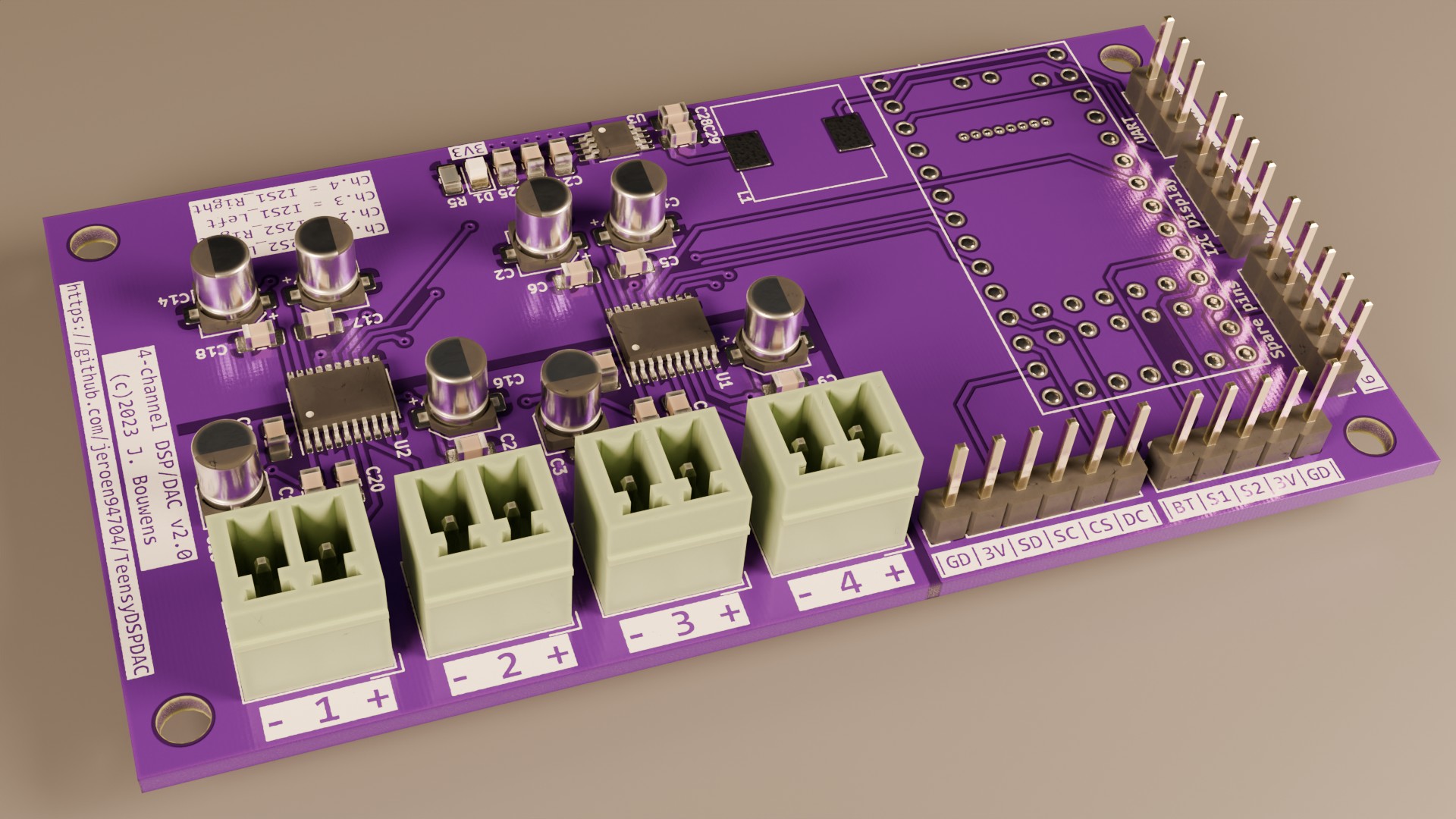
Converting an I2C display to SPI
2023-12-19
When looking for displays to use in both the DSPDAC and Amplifier, I found a couple of 256×64, 2” OLED modules based on the SH1122 controller that looked perfect. Nice resolution, 16-level greyscale, small enough to fit the enclosure. I got them wired up, plugged in the u8g2 library, and they worked! Except for one rather glaring problem: the display was comically slow to update. I could literally watch the image being drawn from top to bottom, taking about half a second to complete.
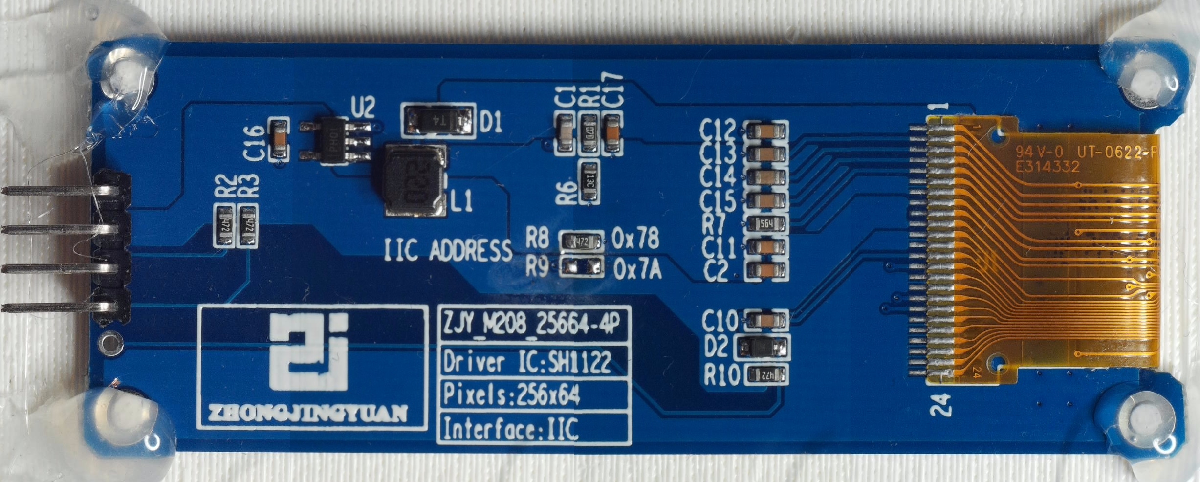
Some back-of-the-envelope maths quickly explained why. The SH1122 is a 4-bit greyscale controller, so a full frame at 256×64 pixels is 256 × 64 × 4 = 65,536 bits of pixel data. At the standard 400 kHz I2C fast-mode clock, and ignoring all overhead, that gives a theoretical ceiling of about 6 frames per second. Once you add the I2C protocol framing and the display controller’s own command overhead, the real-world 2 fps I was seeing makes complete sense. That’s just physics.
I opened a discussion in the u8g2 repository to ask if there was any way out of this. The options on the table were: reconfigure the hardware to use SPI, push the I2C clock beyond 400 kHz using the setBusClock function, or find some hidden 1-bit monochrome mode that might squeeze more speed out of the bus. Library author olikraus confirmed that the SH1122 has no monochrome mode, and that the hardware SPI conversion would be the most impactful fix by far: SPI can run at 8 MHz or more, which is a 20× improvement over I2C.
So I decided to take the hardware route. The display modules are built around a small PCB that have the controller wired for I2C operation by tying certain configuration pins to fixed logic levels and leaving the SPI pins disconnected. This meant the fix was in principle possible: identify which pins needed to change, and make it happen.
The tricky part was the ribbon cable connecting the display glass to the PCB. The SPI chip-select signal (CS, pin 12) was routed along with the rest of the interface signals through this ribbon, but terminated on a track going nowhere. Separating it out and connecting it to the actual SPI CS line required surgery at a scale I wasn’t entirely comfortable with. I ended up very carefully cutting the plastic of the ribbon cable on both sides of the pin 12 pad, desoldering it from the track it was connected to, lifting it up just enough to clear the adjacent pads, and slipping a small piece of tape underneath to insulate it. Not something I would have attempted without my DIY soldering microscope.
It worked. Both display modules are now running in SPI mode and the update speed is night-and-day compared to before: fast enough that you no longer see any tearing or progressive draw. Olikraus called the mod “impressive”, which is a compliment I’ll gladly take.
That said, I wouldn’t recommend this mod to anyone who doesn’t have to do it. It’s fiddly, the margin for error is tiny, and the time investment is significant. The real lesson here is a simpler one: buy SPI displays to begin with. I2C is convenient for microcontroller projects where you’re short on pins and speed doesn’t matter, but for anything that needs to update a full-resolution display repeatedly, SPI is the only sensible choice. I’ll be specifying SPI parts from the start on future projects.
I later recorded the process of doing the second display module: partly for documentation, partly to show just how unpleasant this kind of mod is. You can watch it here.