Jeroen's Project Journals
Kamado temperature controller
A WiFi-enabled temperature controller for my Kamado BBQ
- Gallery
PCB reworked
2024-02-13
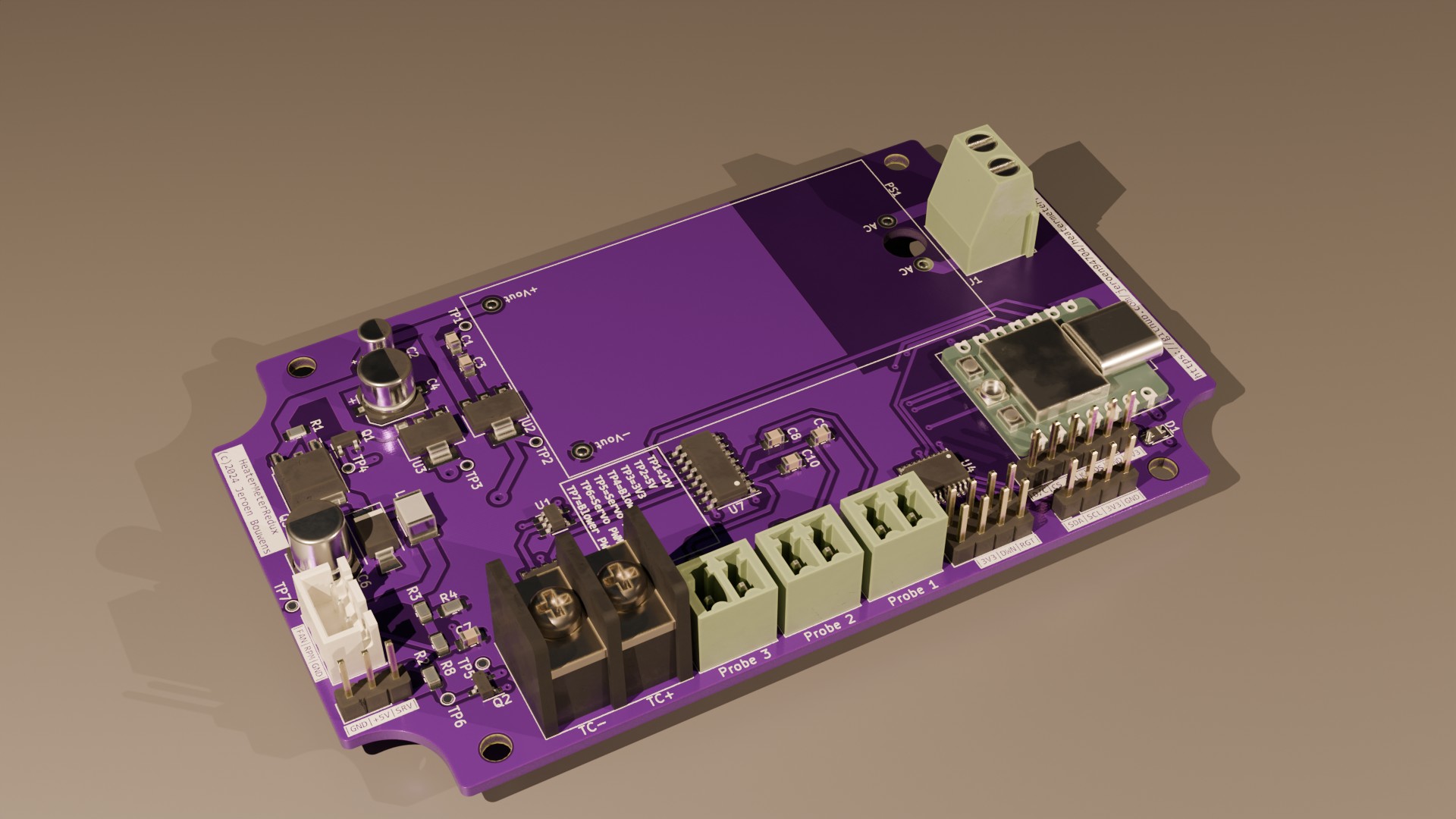
Not everything was well with this design. After the relatively minor issue of the missing blower feedback signal I pressed ahead and wanted to test the thermocouple input by means of the MAX6675 chip. This required a little bit of software work, but unfortunately I quickly discovered that no matter what I did, after uploading the controller would not start normally. What followed was lots of headscratching and many runs with the logic analyzer and scope to understand what was happening. This actually took a couple of evenings, but eventually I figured out the controller was entering USB download bootmode. To understand why, first check this table from the ESP32-C3 datasheet describing the so-called bootstrapping pins:
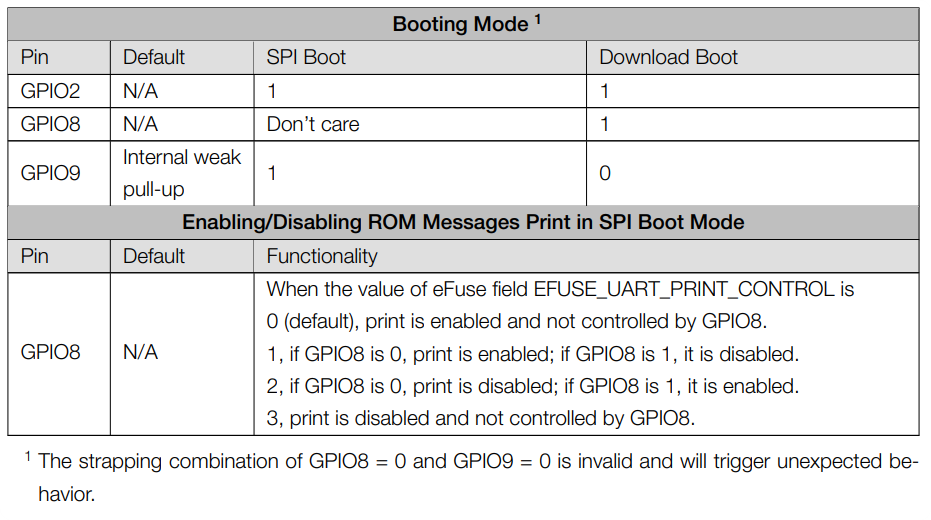
Bootstrapping pins are a way to tell the microcontroller how it should boot: run the program stored in flash memory, load software through the SPI bus (e.g. from an SD card) or wait for a download to start through the USB port. To upload a binary from my PC I need the controller in USB download mode, but otherwise I need the default mode so on power-up the application gets loaded and executed. For this default mode, GPIO9 needs to be left floating, so the internal pull-up is able to pull the pin level high for the duration of the boot process. Now take a look the XIAO pinmap:

You will notice GPIO9 is located on pin D9, which also functions as the MISO pin for the SPI bus! There are 2 devices connected to that pin: the MCP3008 ADC (used to sample thermistor-based temperature probes) and the MAX6675 thermocouple amplifier. Apparently one of these devices was pulling their MISO line low immediately, overpowering the weak internal pull-up and making the controller enter the USB download boot mode. And as it turned out, the MAX6675 was the culprit. Detaching its MISO pin from the signal trace allowed the controller to boot normally.
Initially I was a bit stumped how to fix this, but a helpful commenter on reddit gave me the clue I needed. The solution is to insert a tri-state buffer in the MISO signal between the MAX6675 and the ESP32-C3. This buffer is a logic device that basically connects or disconnects 2 pins depending on an enable signal. Connecting the enable signal to the MAX6675 CS (Chip Select) will hopefully solve this problem.
I say hopefully, because I already ordered new PCB’s with this change (and the SMD caps and change in connectors I described last time) applied.