Jeroen's Project Journals
Introduction
2023-12-16
We’ve lived in our current house for over 15 years now. In the early years I did quite some home improvement projects, and several of those projects involved installing recessed spotlights. The most affordable options back then were kits from Massive, a brand owned by Philips. These kits included 12V halogen bulbs in the GU4 form-factor. Fast-forward 15 years, and 2 things are happening: The 12VDC GU4 bulbs have largely been replaced by 230VAC LED bulbs and the bulbs I installed all those years ago are slowly starting to wear out and fail one at a time. And while I replaced some of those with newer drop-in replacement LED bulbs the original 12V drivers included in the Massive kits are starting to fail as well, causing the LED bulbs to flicker annoyingly.
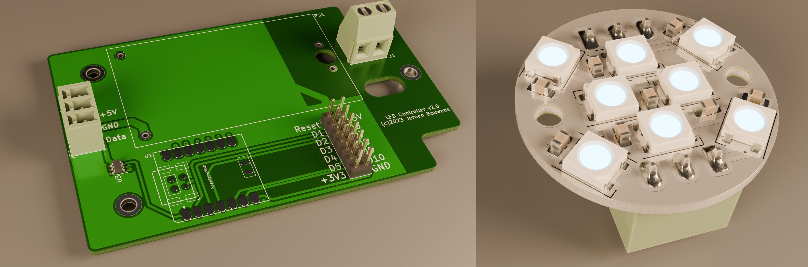
The sensible thing would have been to completely replace the lighting in the affected rooms, but to me this was simply too good an opportunity to ignore and I decided to create my own Smart Home compatible drop-in replacement bulbs. I had some WS2812B addressable LED’s lying around, and in my ignorance started designing a 3D printable spotlight that could hold a single LED and could be mounted in the frames I already have. This wasn’t too difficult, but I VERY quickly realized a single WS2812 was by far not bright enough to replace an actual lightbulb, so after some thought I designed the maximum size circular PCB that would still fit my frames:
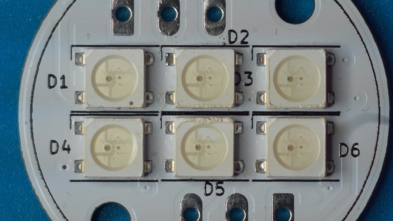
I figured 6 LED’s would surely be bright enough to be usable, and even made provisions to install less than 6, just in case I found this was actually overkill(spoiler alert: it was not overkill, and 6 LED’s is not enough).
At the same time I designed a simple PCB featuring a 20 Watt 230VAC-to-5DC power supply and my new favorite WiFi microcontroller module (the Seeedstudio XIAO ESP32-C3):
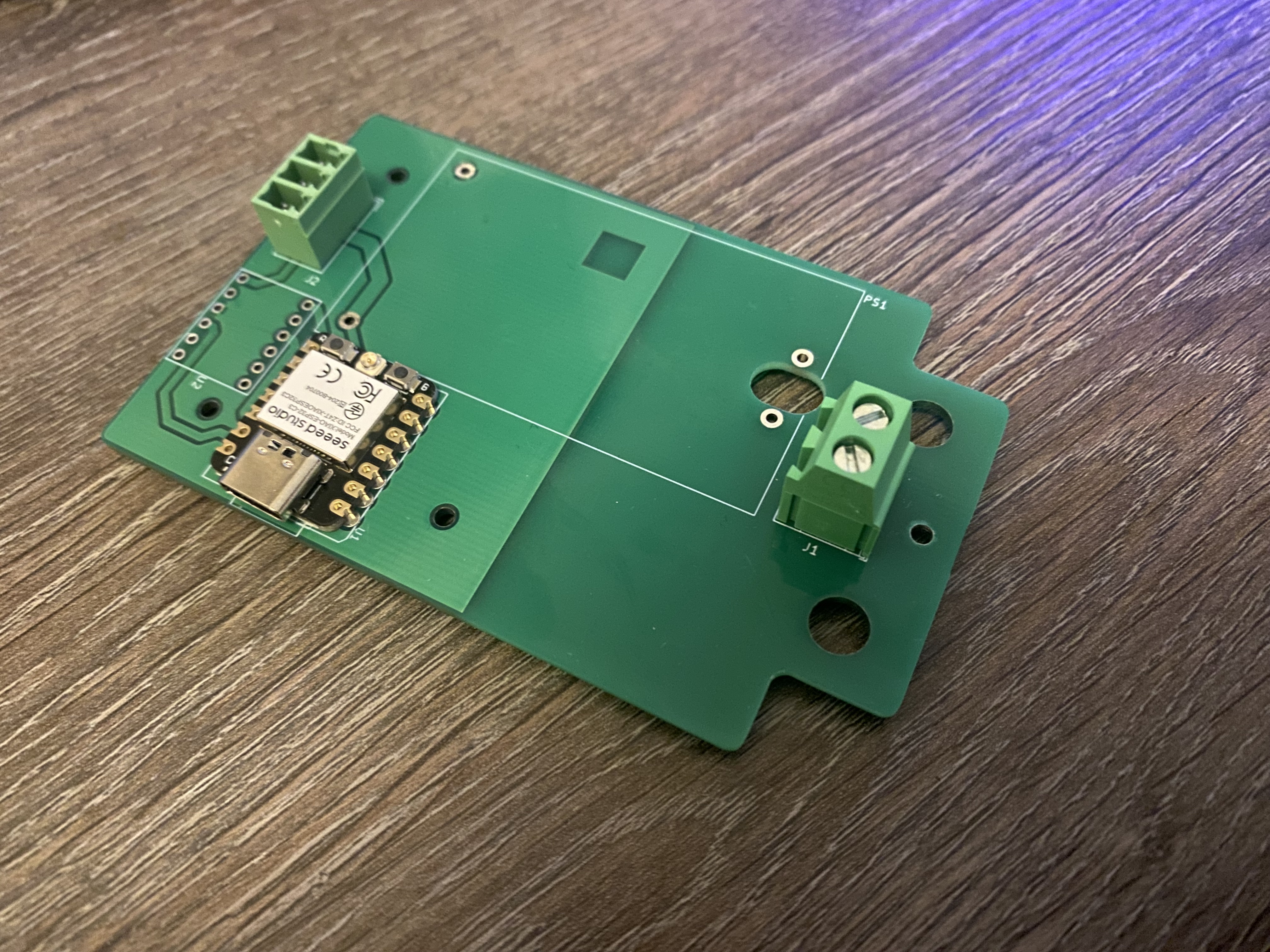
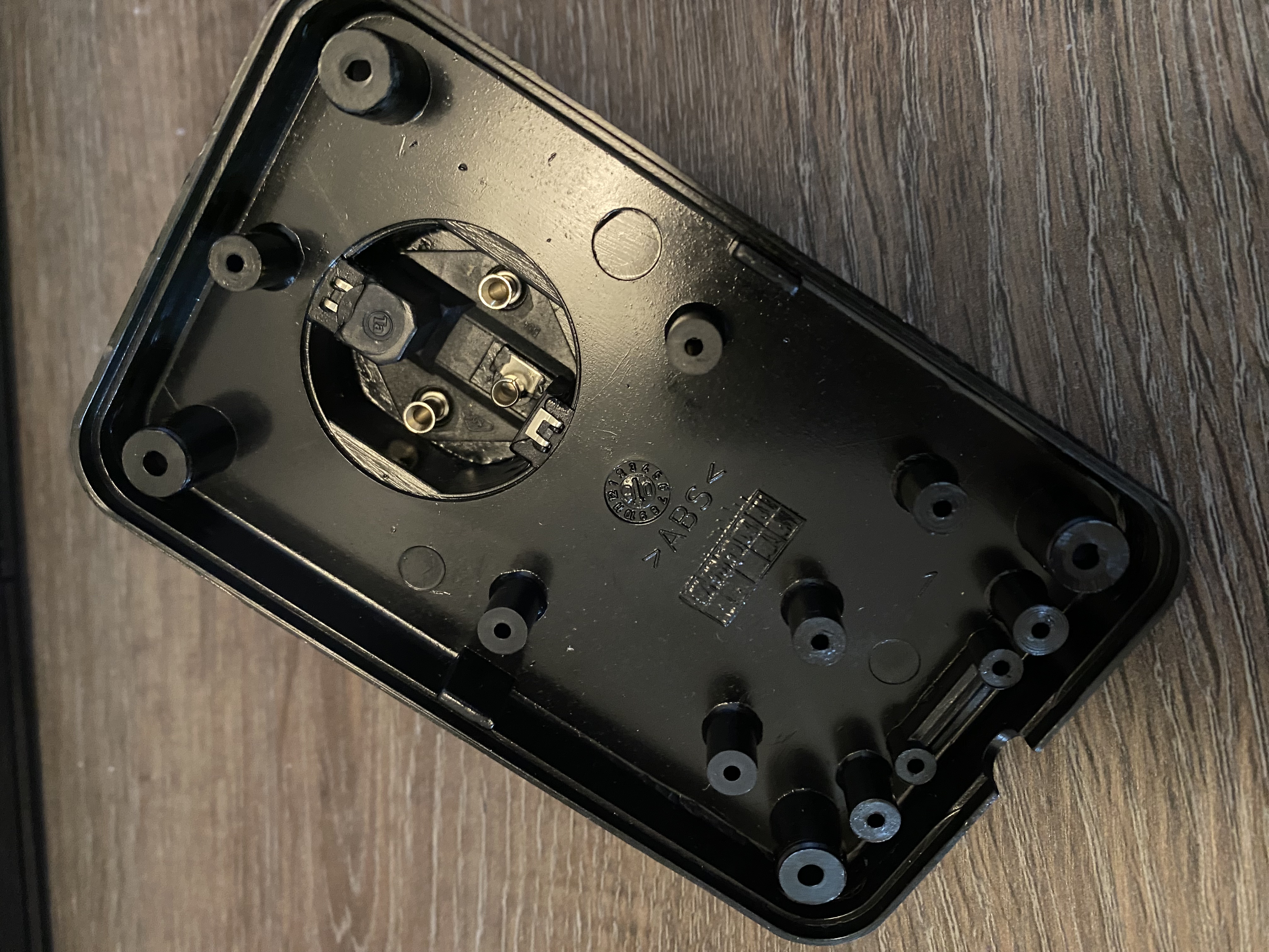
The weird shape is to make it fit inside this plug enclosure I found online:
Since the ESP32-C3 is a 3V3 microcontroller while the WS2812 LED’s need a 5V logic level signal (3V3 sometimes works, but not reliably) I also included a spot for a cheap FET-based level shifter I had in stock. When all the parts had arrived, I could assemble a controller PCB and some of the LED boards (but not before I had completed a side-quest to create a soldering microscope using a gopro I could finally start testing.
Immediately I hit my first roadblock: No matter what I tried, the LED’s refused to produce light. Everything seemed to be in order, voltages looked good, no shorts anywhere. Then I attached a scope to the data-line, and discovered FETs are not a great option for level-shifters. The waveform was distorted beyond what the LED’s could handle. This led to another side-project, which was designing a PCB that:
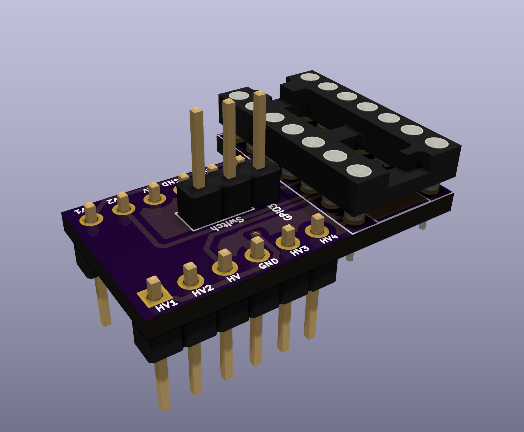
1) Could use the same pinsockets as the original level-shifter 2) Had room for a 14-pin DIP-package level converter chip 3) Fit inside the enclosure 4) Included connections for an external switch, which I completely overlooked in my original design
These constraints led to my jankiest PCB design to date:
2 weeks later these PCB’s arrived and fortunately this seemed to fix the issue (spoiler alert: BUT …), so now I could finally assemble the remaining LED PCB’s, screw the controller in the enclosure and start installing the system in my daughter’s room.
Or so I thought.
Very quickly I discovered I had overlooked a critical thing: the mains power-socket for this lighting system is behind a low ceiling, which I had cleverly placed close to one of the holes in which the spots are installed, and the plug-enclosure did not fit through that hole! Enlarging this hole enough for the enclosure to fit would leave it too large for the frame to cover it up, so that was not an option.
So everything came back down, I ditched the plug enclosure and quickly designed an enclosure that could squeeze through that hole AND fit the controller PCB. A week later I had everything back upstairs and I could finally install the lighting.
Well … most of it anyway.
There are 9 spots, and I replaced 6 of them with. For the final 3 I needed to run the cable through a small hole drilled through a massive wooden beam. The plan was to use the original cable to pull the new cable through, but I pulled a bit too hard and the new cable slipped off, so now I have to figure out a way to find that tiny hole that is impossible to reach without tearing out part of the ceiling.
Oh, and it turns out even with 6 LED’s per spot the brightness is insufficient to properly light the entire room.
And after a week the level-shifter broke down, so I had to replace it.
And for some reason after another 2 weeks half the LED’s stopped working. Except when I operate the powered shutters, then they sometimes suddenly kick in.
So, all in all, not a great result.
In the meantime I redesigned the LED PCB to hold an extra 2 LED’s and some stabilizing capacitors. I also redesigned the controller PCB to include a proper level-shifter, although I just realized I could try using a single WS2812 LED as levelshifter instead, since each LED reconditions the data signal before forwarding it. I suspect the problems with half the LED’s no longer working are due to ringing in the data line, since I did not include a series resistor as recommended online, so I can try adding one to see if that helps.
In the end though, all of this is a lot of effort to get full-room RGB lighting, while it turns out that 99% of the time the best lighting is just solid, non-animated and single-color. So I’m also looking into ditching the WS2812’s and using a single fixed-color power LED per spot.
To be continued.