Jeroen's Project Journals
Audio amplifier
3-channel audio amplifier. Mains-powered and with digital volume control. Includes a 3D printed enclosure matching the Teensy DSP/DAC, OLED display and rotary click-encoder control
- Gallery
More issues fixed
2024-08-29
Finally! As I am typing this I am in fact listening to music through the amplifier, but getting here was not without headscratching and some strong language:
First I did pretty much exactly what I described previously to add the level-shifter to the PCB: Cut the I2C traces, scrape away the solder-mask, hot-glue the level-shifter to the board and solder up some wires. The result is this amazingly professional-looking patch, which actually worked straight away, which was nice:

Then I soldered the XIAO ESP32C3 module in place. This is the microcontroller board the PCB was designed for, but I used the S2 mini for testing since that is bread-boardable. This worked too (shout-out to PlatformIO for making it easy to switch between microcontrollers!). So then I tried adding the rotary encoder to control the volume, and I ran into an issue: with the encoder connected the micro refused to startup properly. It took me way too long to realize I got bitten by bootstrapping pins once again! This seems to happen in every one of my projects, which means I can simply refer to another post for an explanation.
In this case, the pull-up behavior of the rotary encoder pulls GPIO2 (D0) high immediately upon booting, causing the ESP32 to enter SPI boot mode. I can patch this to switch to another pin (D3 is currently unused), but I suspect I’ll have a similar issue with GPIO8 and/or GPIO9, which are the SCK and MISO pins for the SPI display. Everything is fixable of course, but the amount of patching required is horrible, so I’ll probably end up ordering a revised version of the board.
Leaving the rotary encoder behind for a bit I decided to finish assembling the rest of the board and hard-code a reasonable value for the volume so I could at least enjoy some music. When I finished soldering I plugged in the power and … nothing … for a little bit. Then I started smelling that smell, and I suddenly noticed the power supply was feeding over 2 amps into the board. Long story short: I had reversed the polarity of the power wires, and since the board does not have a protection diode this fried the 5V regulator.
So I replaced the regulator, fixed the power wires, plugged in the power and … nothing again! More headscratching, more scope and multimeter action, and then I figured out the amplifiers were in mute mode. Somewhere along the line I soldered all pins of the XIAO to the board, including the mute pin, which apparently gets pulled high by default, causing the amplifiers to be muted.
A quick software fix to unmute after power-up, upload to the board, plug in a single amplifier module, power up the board and play some music. AND IT WORKED! So I powered down, plugged in the other 2 amplifiers, wired up all speakers, powered up once more and … a DEAFENING screeching sound! This was bad, as I could actually SEE the loudspeakers getting pushed out to their maximum excursion distance, which is really bad for them. Some very careful experimentation ensued and I quickly found out that it worked fine with a single amp module, but not with more than one.
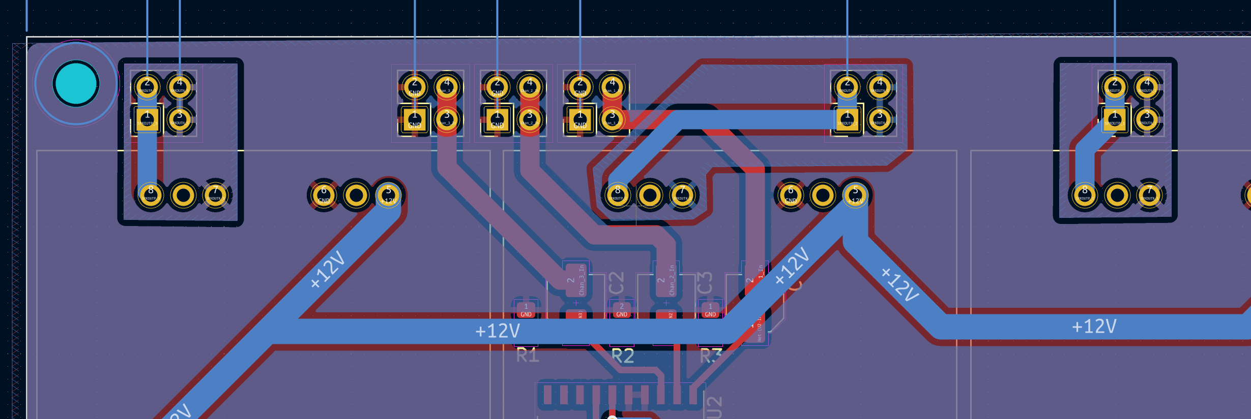
I was a little discouraged at this point, and I set the board aside for a couple of hours. The mind works in mysterious ways though, because while relaxing on the couch I suddenly realized what was going on. What’s more, I had already fixed this issue in the revised design I had been working on in parallel. The current version of the board has all analog grounds tied together, since that made sense to me at the time, and it’s what the reference design in the datasheet of the PT2258 does too. But I later realized the reference design in the datasheet of the amplifier chip doesn’t do this for the output signal. So I had already updated the design to isolate the positive and negative output signals of the amplifiers from everything else. This is also effectively how things were wired before I designed the carrier board:
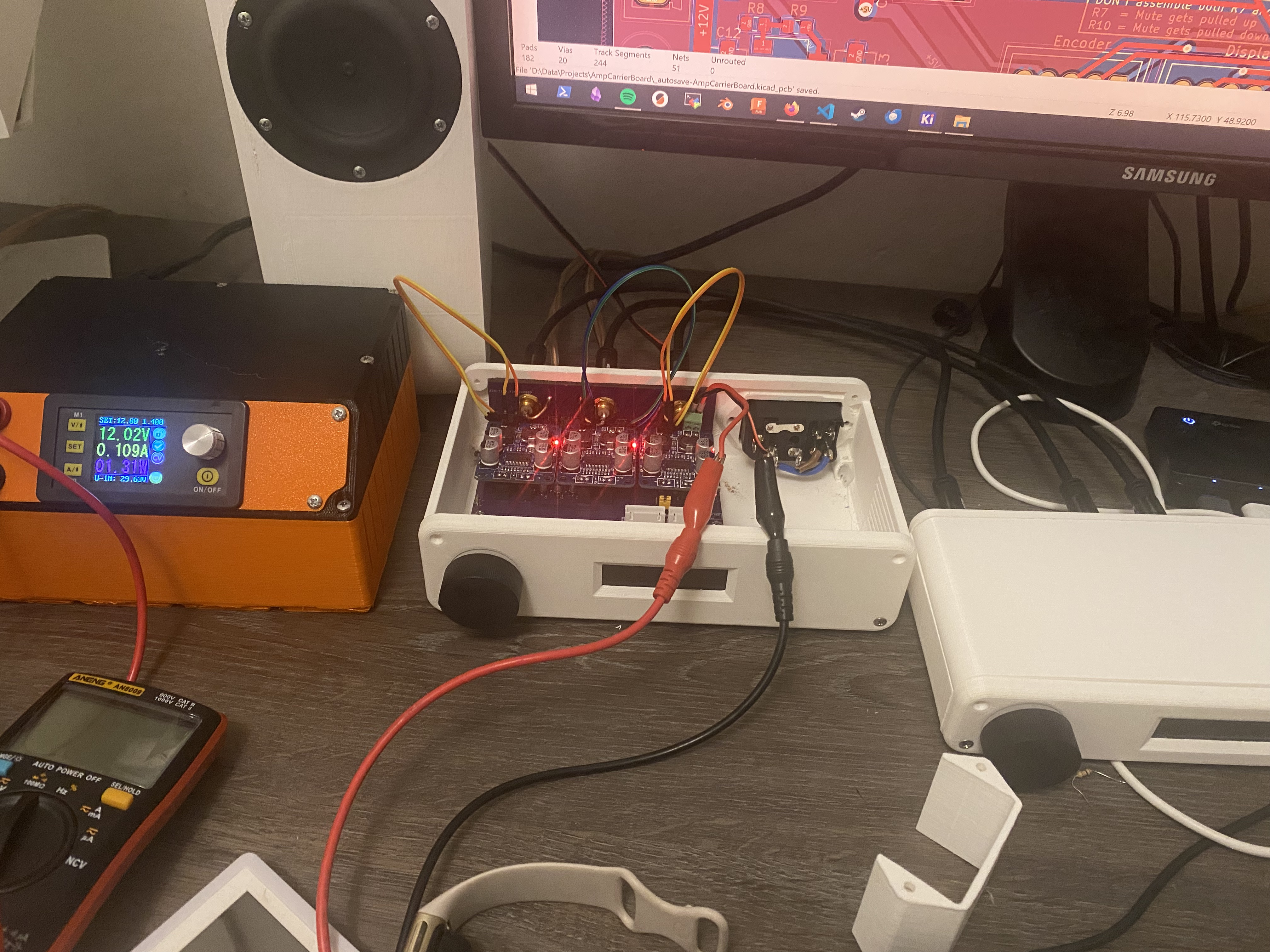
To test this idea I removed the downward-pointing pinheaders of the amplifier modules’ output signals and temporarily connected them using patch cables. This worked, proving my hypothesis was correct. It also means I’ll definitely order a new board, since this is just a bit too much patching, even for me! I’ve already updated the design with all the todo’s I listed previously, but before I can place the order I need to:
- Figure out what to do with the encoder signals
- Verify if I do or do not have the same issue with the SPI MOSI and SCK pins and fix that if needed
- Add a reverse-polarity protection diode
- Do something about the power-down sequence, since it currently gives a loud POP when I switch off the power
Also, I still need to modify the I2C OLED display so it works with SPI, which I already did with the one used in the DSP/DAC (read about it in this GitHub thread). That’s going to be interesting!
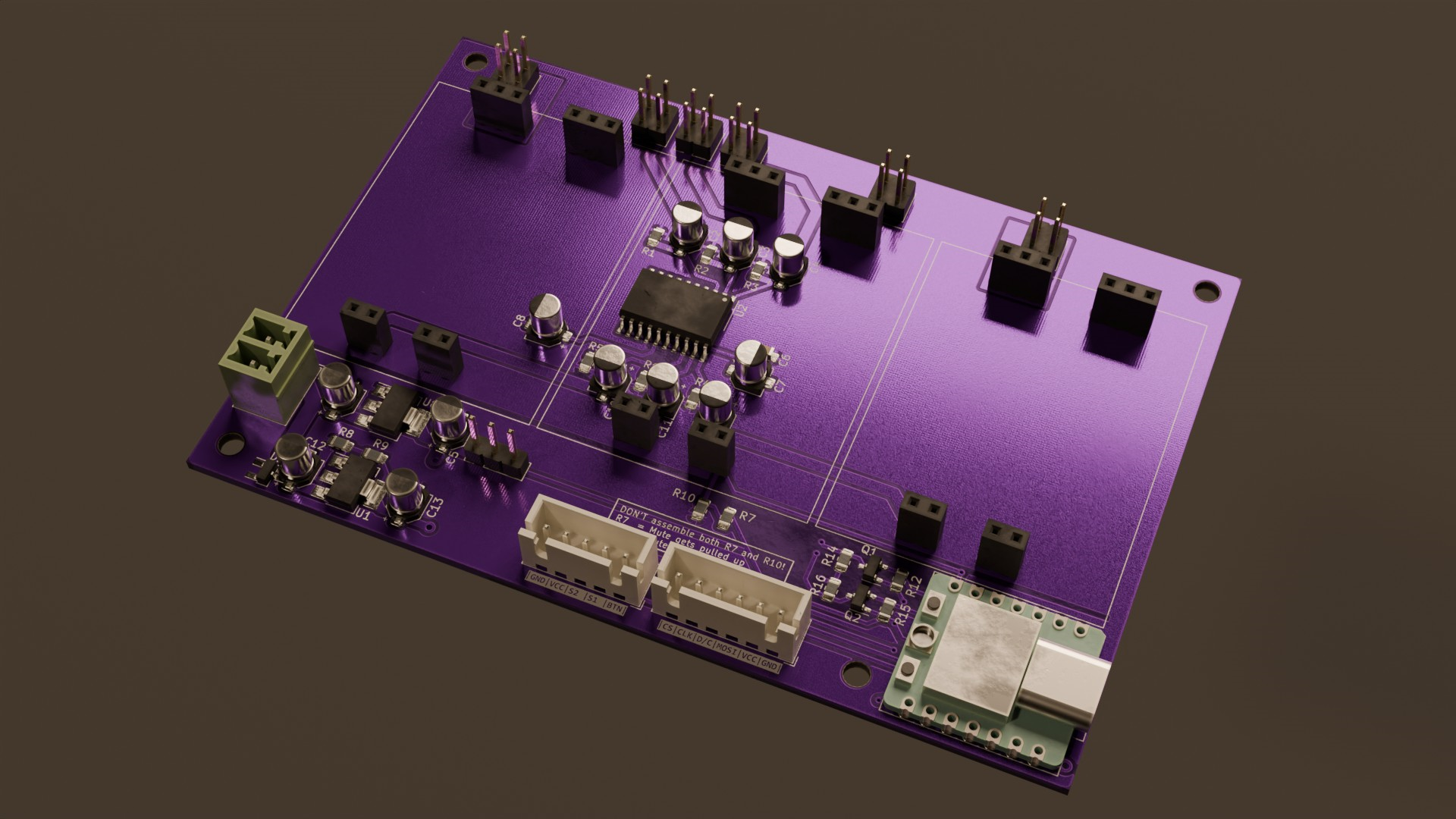
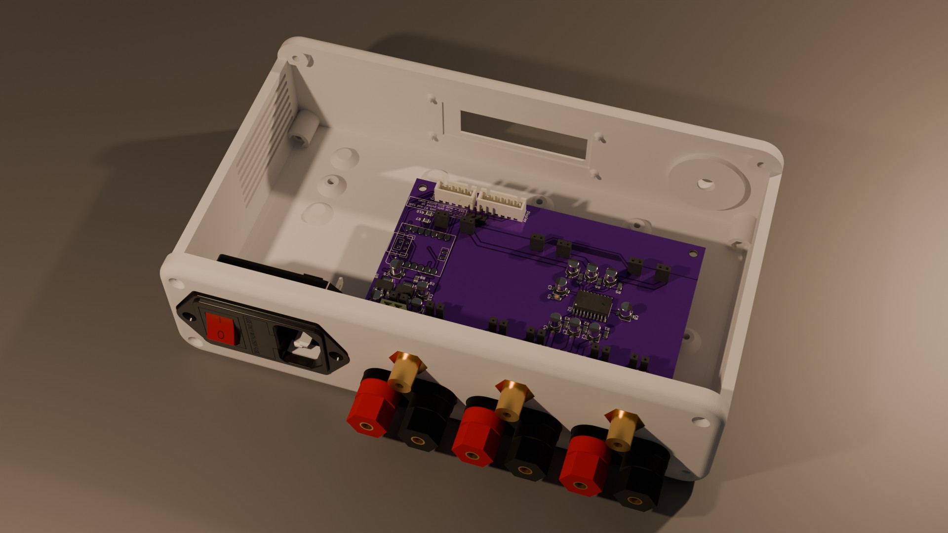
I’ll end this with a render of the updated design as it is right now, mainly for eye-candy: